skoda Workshop Repair Guides

Skoda Workshop Service and Repair Manuals

Replacing O-rings of unit injector for engine with engine identification characters BKD, AZV > < Removing
Install
Install
  Caution
l  For any work procedure involving an adjustment of the unit injector via the adjusting screw, it is necessary to replace the adjusting screw in the valve lever and the ball pin of the unit injector, otherwise this can lead to considerable wear of these components.
l  The fixing screws of the unit injectors must definitely be replaced as well.
  Note
t  When installing, oil the O-rings and the lines in the cylinder head.
t  New unit injectors are supplied with new O-rings.
t  If the old unit injectors are installed again, all O-rings must be replaced → Chapter.
t  Grease the contact surfaces of the ball pin and the adjusting screw using Grease - G 000 100-.
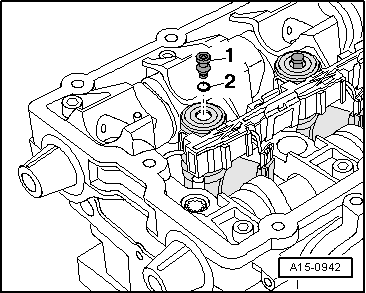
–  Before installing the unit injector check the correct position of both O-rings.
l  The O-rings must not be twisted.
l  The white marked O-ring is located in the bottom groove of the unit injector.
–  Oil O-rings and shank of the unit injector.
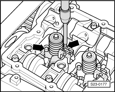
–  Check seat of unit injector in cylinder head for any dirt or foreign bodies (swarfs/carbon deposits etc..) and if necessary clean with compressed air.
–  Insert the unit injector with the greatest of care into the cylinder head seat.
   
–  Fit assembly device for valves -2036- with the retaining plates -2036/1-, as shown, onto the bearing frame of the cylinder head.
  Note
If the fixing plates -2036/1- cannot be fitted due to the exhaust gas recirculation radiator, place large body washers underneath.
  N23-10184
–  Position new fixing screws using socket insert -T10054- and carefully screw in without using force up to the stop -arrow-.
  Caution
If the unit injector is pulled down by the fixing screws, there is the risk that the unit injector is pulled skewed into its seat. This can result in poor vehicle handling and starting problems. For this reason the unit injector must be pressed into its seat and must only then be screwed on.
  N23-10185
–  Position valve lever -VW 541/1 A- with pressure plate -VW 541/5-.
–  Carefully press the unit injector into its seat with the valve lever and hold with a force.
–  Screw in fixing screws of the unit injector carefully and without using force up to the stop.
  N23-10186
–  Tighten screws of unit injector -arrows- alternatively as follows with a socket insert -T10054-:
  S23-0177
StageTighten
I
–  Tighten with the torque wrench to 3 Nm.
II
–  Using a rigid wrench torque a further 270° (3/4 turn).

  Note
The torquing angle of 270° must absolutely be carried out in one working step!
   
–  Before inserting the valve-lever shaft, check whether all the ball pins -1- and O-rings -2- are inserted in the unit injectors.
  A15-0942
–  Screw on valve-lever shaft with new screws as follows:
  A23-0212
SequenceTighten
I
–  Tighten screws -2- and -4- alternatively in several stages, until the valve-lever shaft rests on the bearing frame.
II
–  Tighten screws -1-, -3- and -5- to 20 Nm and torque a further 90° (1/4 turn).
III
–  Tighten screws -2- and -4- to 20 Nm and torque a further 90° (1/4 turn).

   
–  Place a dial gauge, as shown, onto the adjusting screw of the unit injector.
  Caution
Spin the engine at the crankshaft only in direction of rotation of engine (in clockwise direction).
–  Turn the crankshaft in the running direction of the engine until the roller of the roller rocker arm is on the drive cam tip.
l  Roller side of roller rocker arm -arrow A- is on the highest point.
l  Dial gauge -arrow B- is on the lowest point.
–  Remove the dial gauge.
–  Turn the adjusting screw in the roller rocker arm until one feels a significant resistance (the unit injector is against the stop).
  S23-0221
–  Turn the adjusting screw in the opposite direction from the stop by about 180°.
–  Hold the adjusting screw in this position and tighten up the lock nut using a torque of 30 Nm
Further installation occurs in reverse order to removal. Pay attention to the following:
–  Mount plug for unit injectors and for glow plugs.
–  Fasten retaining clips.
–  Install cylinder head cover → Chapter.
  A23-10120

Replacing O-rings of unit injector for engine with engine identification characters BKD, AZV > < Removing